This tutorial applies to the Windows desktop version of ArchiTech Sketchpad.
All interaction principles regarding drawing, editing and project handling are identical for the Windows Phone App. Differences only affect the arrangement of the app toolbar and the layout of the Settings/Save&Load/OneDrive pages.
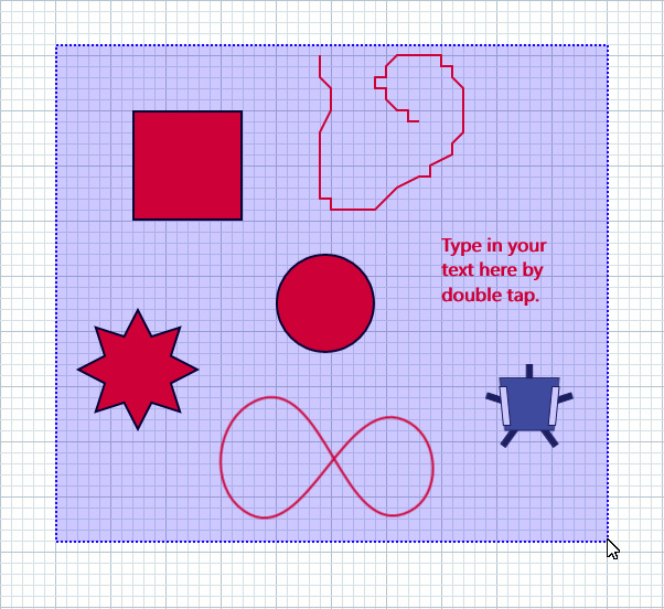
Available Objetcs
ArchiTech Sketchpad is intended to create professional vector-based drawings. Thus, the App is intended for architects, engineers as well as for graphic designers.
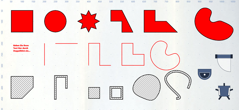
Therefore, a wide range of geometrical objects is available which are essentially divided into the following categories:
Shapes ♦ Drawing objects ♦ Path objects
Form objects
Shapes are composed of geometric figures. A shape is created by positioning the finger on the artboard to define the starting point and dragging diagonally until the desired size is reached. This category includes rectangles, circles, stars, text objects, vertical and horizontal lines and numerous furnishings.
Drawing objects
Drawing objects consist of several path segments defined by individual anchor points. This category includes freehand shapes and freehand lines. Drawing objects are created by drawing the line on the artboard freehand.
Path objects
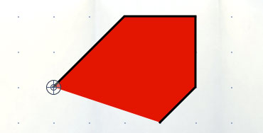
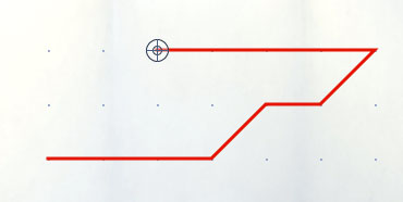
Path objects consist of several path segments defined by individual anchor points. This category includes polygon objects, Bezier spline shapes, polylines, Bezier splines, polygonal spaces and walls. Path objects are created by tapping the artboard one after the other to create individual anchor points.
Objects (with the exception of star shapes) can be modified to change the path. To do this, the editing mode must be activated by double tapping an object. In this mode, the individual anchor points and path segments become visible. The anchor points can now be moved or deleted; new points can be added to the path object.
2. TOOLBAR ⮟
Application bar
The App toolbar is the primary tool of the application. It provides several icons to create all kinds of geometry objects. These are divided into four main categories:
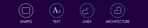
Fill areas ♦ Text ♦ Lines ♦ Architecture objects
Objects of the application bar
Tapping an icon in the toolbar opens the corresponding submenu. This provides specific subcategory icons to select the desired geometry object.
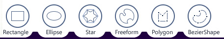
Rectangle ♦ Ellipse ♦ Star ♦ Freehand form ♦ Polygon ♦ Spline shape

Text
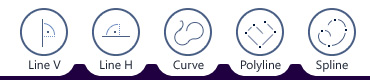
Vertical line ♦ Horizontal line ♦ Freehand line ♦ Polyline ♦ Bezier spline
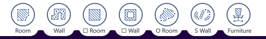
Rectangular room ♦ Rectangular wall ♦ Spline room ♦ Spline wall ♦ Room ♦ Wall ♦ Interior
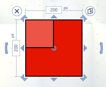
3. BOUNDING BOX ⮟
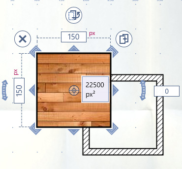
Bounding box handles
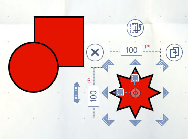
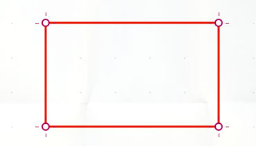
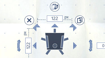
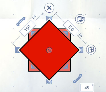
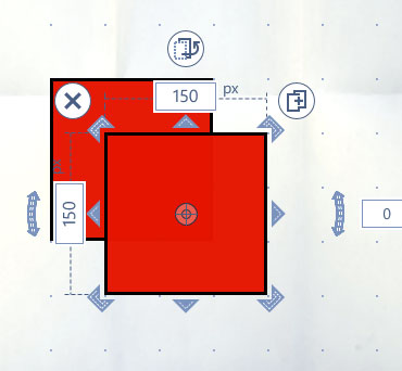
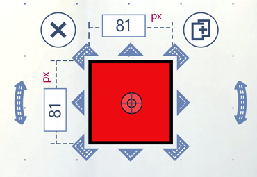
When an object is activated, it is equipped with the so-called “Bounding Box”. This interactive control provides multiple handles and buttons to modify the object.
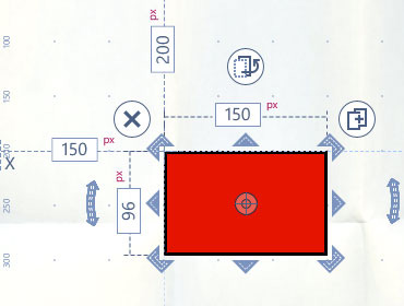
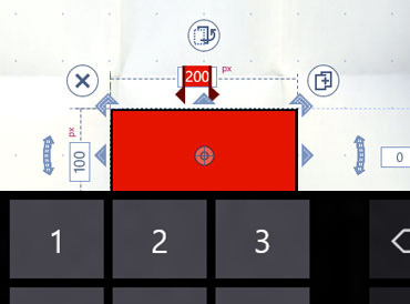
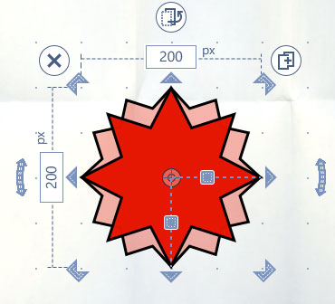
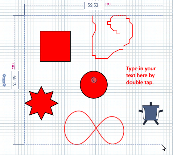
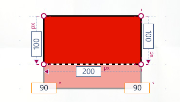
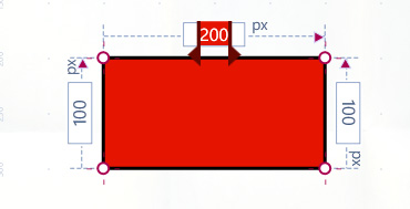
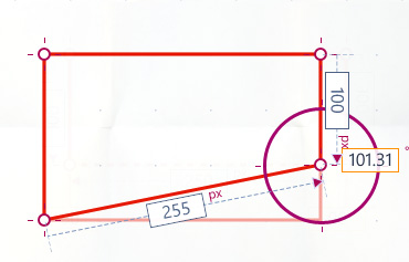
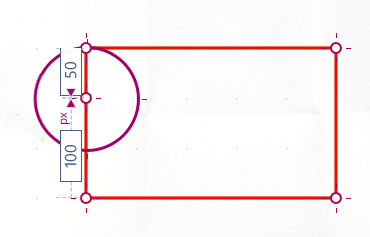
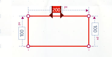
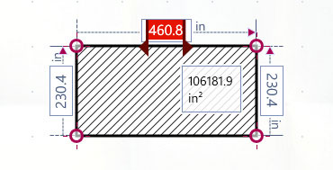
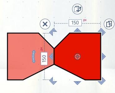
In addition, the bounding box provides several input fields which display parameters such as width, height, and rotation angle of the activated object.
Scaling handles ♦ Rotation handles ♦ Delete button ♦ Arrange button ♦ Clone button
Bounding box input fields
To change an object parameter, the corresponding input field must be tapped to make it editable. The virtual keyboard opens and the new value can be entered directly.
Bounding box sliders
The bounding box of star shapes offers two further sliders to set the number of spikes and their radius.
4. SELECTING OBJECTS ⮟
Multi-Selection
In addition to single selection, you can also select several objects at the same time. A separate selection mode is available for this purpose, which enables both, single selection and multi selection of objects.
This functionality can be activated in the upper toolbar by clicking the first icon:

Selection Area
Multiple selection is to be accomplished by dragging a selection rectangle over the objects to be selected.
If you draw this rectangle from top to bottom, it appears blue-purple. This means that the objects to be selected must be completely included in the selection rectangle.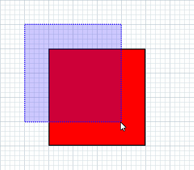
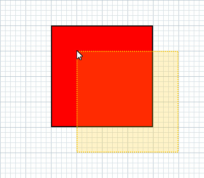
If you draw this rectangle from bottom to top, it will appear yellow. This means that at least one point or side of the object must be included in the selection rectangle to be selected.
Multi-Edit
Multiple selected objects are equipped with a comprehensive bounding box, which allows you to rotate, move or delete objects together.
5. SHAPES ⮟
Fill areas


The first type of geometry objects are fill areas that are composed of a colored filling and a black outline. According the main principle they are divided into three categories: shape objects, drawing objects and path objects.
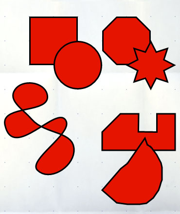
Rectangle ♦ Ellipse ♦ Star ♦ Freehand shape ♦ Polygon shape ♦ Bezier spline shape
Creating fill areas of the type form object
Shapes such as rectangles, ellipses and stars are created by dragging diagonally on the artboard until the desired size is reached. The special types ‘square’ and ‘circle’ can be created by activating the option ‘proportional scaling’ in the App settings.
Editing fill areas of the type form object
Path objects such as polygon and spline shapes are created by tapping on the artboard to create the individual anchor points of the path object.
6. EDITING SHAPES ⮟
Edit fill areas of the type path object


To modify an object the edit-mode has to be activated by tapping on an activated object. In this mode the single anchor points become visible and can be changed.
Moving points and segments
If a single point or segment is tapped, it can be moved to the desired position.
Adding points and delete points
In the ‘edit mode’ there are additional icons in the App toolbar, which can be used to add or delete individual anchor points.


Add point ♦ Delete point
By tapping on the ‘+point’ icon, the ‘point creation mode’ is initialized. To add another point to the path, tap the corresponding segment at the desired position. A new point is inserted.
When you tap the “-point” icon, the ‘point delete mode’ is initialized. By tapping an existing point, it can be deleted from the path.
Tapping an activated icon in the App toolbar again terminates all modes.
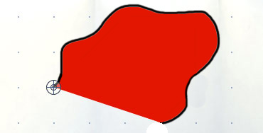
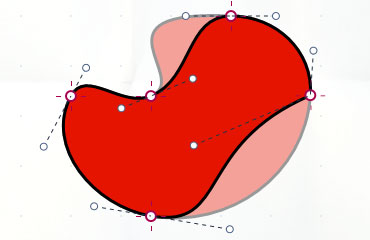
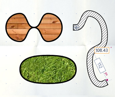
Edit curve points
Double tapping a Bezier Spline object makes the individual anchor points and the Bezier handles visible. They define the curve progression of the corresponding segment. To adjust the smoothness of the curve, the corresponding Bezier handle must be tapped and dragged into the desired position.
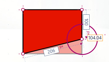
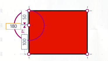
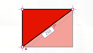
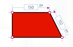
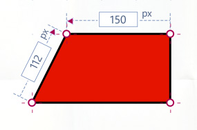
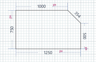
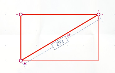
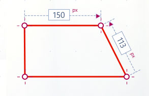
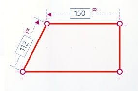
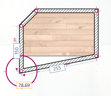
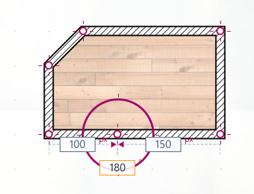
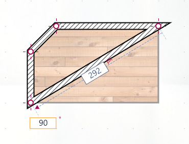
Editing lengths of segments
To change the segment length, a point or a segment has to be tapped to display the dimension lines and input fields. Tap an input field to access the virtual keyboard. The new value can be entered directly.
7. TEXT ⮟
Text objects

The second type of geometry objects is the text object of the type shape. Correspondingly, it is created by diagonal dragging until it reaches the desired size. Initially, a dummy text is displayed.
By double tapping on a text object the ‘edit-mode’ is initialized and the text content can be changed.
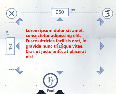
Editing text objects
The font can be changed by selecting the desired typeface. This can be selected in the lower font list which opens in the edit-mode.
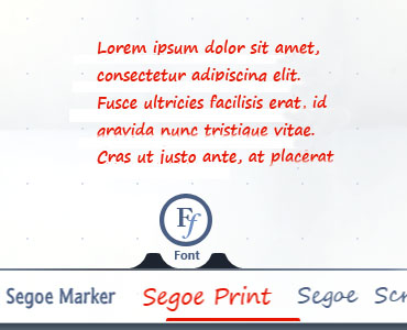
Setting font styles
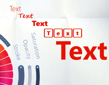
A long press on the text object opens the color picker. The color of the text can be changed by tapping the desired color slice. Additionally, the saturation as well as the font size and the opacity can be changed using the three sliders.
8. DIMENSION LINES⮟
Creating dimension Lines (coming soon!)

Dimension lines are created like polygon objects by tapping on the artboard to create multiple anchor points. They can consist of one or more segments. To close a dimension line, the starting point has to be tapped again. If it should remain open, you have to tap the last created point again.
Dimension lines are objects for dimensioning all CAD objects. Unlike temporary dimension lines, which appear on the Bounding Box or on a path segment when an object is activated, dimension lines and their values are always visible and can be printed.
Dimension lines are used optimally when the ‘grid snapping’ option is activated.
In the edit mode, a slider is available on the first segment of a dimension line. This allows you to change the distance between the text box and the baseline axis of the dimension line.
A red-purple button with a double arrow is also visible in the edit mode. By tapping this button, the text box of the dimension line is switched to the other side of its baseline axis.
In the edit mode, the individual path points and segments of a dimension line can be edited. They can be moved, added or deleted. By entering a value in a text bos of a segment, it can be extended or shortened.
9. LINES ⮟
Lines of the type form object


A straight line is of the ‘drawing object’ type and can be created by dragging horizontally or vertically on the artboard until it reaches the desired size.
Lines of the type path object

Freehand lines are ‘drawing objects’ and can be created free-handed by ‘drawing’ on the artboard in any direction.


Polylines are of the ‘path objects’ type . They are created by tapping on the artboard to generate the individual anchor points. These lines are finished by either tapping on last created point to keep the path open, or by tapping the starting point to close the polyline.
10. EDITING LINES ⮟
Edit lines of the type path object
To modify an object, the edit-mode must be activated by tapping on an activated object. In this mode the single anchor points become visible and can be modified.
Moving points and segments
If a single point or segment is tapped, it can be dragged to the desired position.

Adding points and delete points
In the ‘edit mode’ there are further icons in the bottom toolbar available which are intended to add or delete single anchor points.
Add point ♦ Delete point
By tapping on the ‘+point’ icon, the ‘point creation mode’ is initialized. To add another point to the path, tap the corresponding segment at the desired position. A new point is inserted.
When you tap the “-point” icon, the ‘point delete mode’ is initialized. By tapping an existing point, it can be deleted from the path.
Tapping an activated icon in the App toolbar again terminates all modes.
Editing curve points
Double tapping a Bezier Spline object makes the individual anchor points and the Bezier handles visible. They define the curve progression of the corresponding segment. To adjust the smoothness of the curve, the corresponding Bezier handle must be tapped and dragged into the desired position.
Editing lengths of segments
To change the segment length, a point or a segment has to be tapped to display the dimension lines and input fields. Tap an input field to access the virtual keyboard. The new value can be entered directly.
11. ARCHITECTURE ⮟
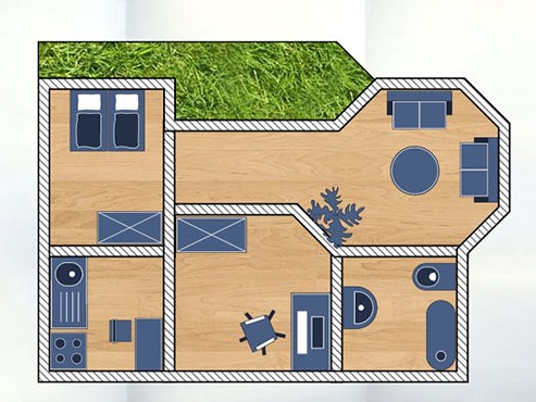
Architectural objects


The fourth type of geometry objects are architectural objects which include rooms, walls and pieces of furniture. According to the main principle they are divided into three categories: shape objects, drawing objects and path objects.
Creating path objects
The creation of polygonal rooms and walls is similar to other path objects. They are created by tapping on the artboard to generate several anchor points.
polygon room ♦ polygon wall
Polygonal and Bezier spline walls can be closed by tapping the start point. To finish the wall without closing the path, tap the last point again.
Closing at start point ♦ closing at end point
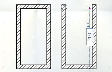
Rectangular path objects
The first type of rooms and walls are of the shape object type. They are created by dragging diagonally on the artboard until they reach the desired size.
Spline path objects
Bezier spline rooms and walls are path objects. They are created by tapping on the artboard to generate the individual anchor points.
12. EDITING ARCHITECTURE ⮟
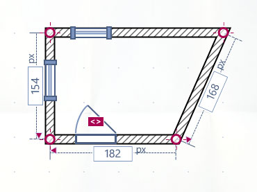
Creating rooms and walls
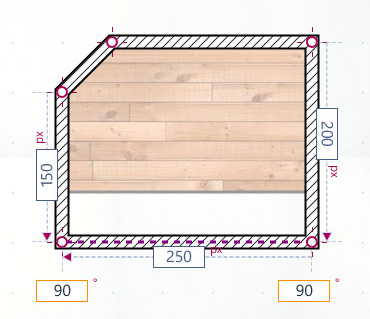
To modify an object the edit-mode has to be activated by tapping on an activated object. In this mode the single anchor points become visible and can be changed.
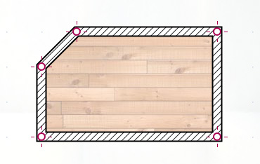
Moving points and segments
If a single point or segment is tapped, it can be moved to the desired position.
Adding points and delete points
In the ‘edit mode’ there are additional icons in the App toolbar which are intended to add or delete individual anchor points.
Add point ♦ Delete point
By tapping on the ‘+point’ icon, the ‘point creation mode’ is initialized. To add another point to the path, tap the corresponding segment at the desired position. A new point is inserted.
When you tap the “-point” icon, the point delete mode is initialized. By tapping an existing point, it can be deleted from the path.
Tapping an activated icon in the App toolbar again terminates all modes.
Editing curve points
Double tapping a Bezier Spline object makes the individual anchor points and the Bezier handles visible. They define the curve progression of the corresponding segment. To adjust the smoothness of the curve, the corresponding Bezier handle must be tapped and dragged into the desired position.
Editing lengths of segments
To change the segment length, a point or a segment has to be tapped to display the dimension lines and input fields. Tap an input field to access the virtual keyboard. The new value can be entered directly.
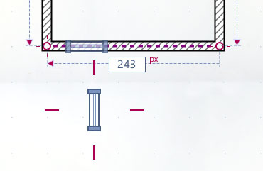
13. OPENINGS ⮟
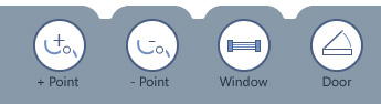
Creating openings


Openings can be created in segments of straight walls.
Creating doors and windows
To create openings, double-tap the activated wall to initialize the edit mode. The toolbar opens, which provides two icons for doors and windows. If the desired opening icon is tapped, the opening can be positioned in the wall segment by tapping on the demanded position.
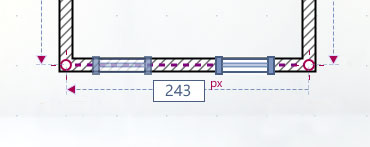
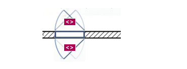
Moving openings
An opening can be modified in the edit-mode of a path object. It provides an input field for the opening width. It must be tapped to change the related value.
An opening can be moved along a wall segment by dragging it to the target position or to another wall segment.
Deleting openings
To delete an opening, it must be dragged out of the wall at any position until it disappears.
Modifying openings
The door swing can be adjusted using the purple toggle button, which becomes visible in the edit-mode. The door swing can be switched in the opposite direction or the other side of the wall by tapping the toggle button until the desired state is reached.
14. INTERIOR ⮟
Furniture

To create pieces of furniture for rooms, the app provides a wide range of interiors.
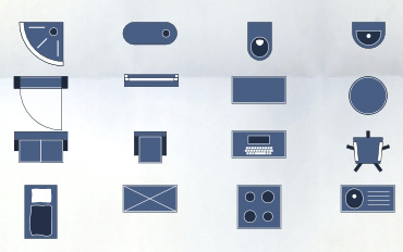
Creating furniture
Furniture can be found in the architectural objects menu of the App toolbar. By tapping on the furniture icon, the submenu opens to offer numerous pieces of furniture.
Furniture is of the shape object type. A piece of furniture is created by dragging diagonally on the artboard until it reaches its desired size.
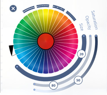
15. COLORS ⮟
Defining colors of objects
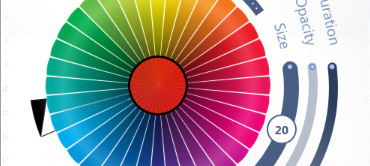
The color picker offers a wide range of colors to set the fill color of shapes or the stroke color of lines. The color can be applied to the object by tapping the desired color slice.
Longpress directly on the artboard opens the color picker. The color selection is applied to objects created in the next step. If you hold your finger directly on an activated object, the color selection is applied directly to that object.
In addition, three sliders are available to adjust the saturation, line width and opacity of an object.
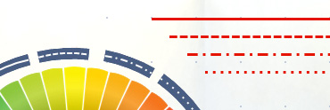
Defining line styles
The color picker provides four buttons to set the style of the stroke. Available types are a solid line and three types of dashed lines. The desired style is applied to the activated object by tapping one of those buttons.
Handling the color picker
The color picker can be dragged anywhere on the screen.
Defining text styles
Longpress on the text object opens the color picker. The color of the text can be changed by tapping on the desired color slice. Additionally, the saturation as well as the font size and the opacity can be changed by the three sliders.
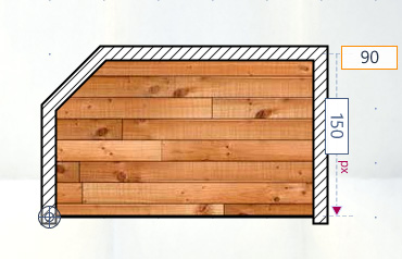
Textures of rooms and walls
These principles apply to the pattern picker. If you hold your finger directly on an activated room or wall, the selected pattern will be applied to exactly that object. Holding the finger directly on the artboard, the selected values are applied to further created objects.
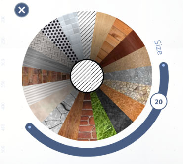
The pattern picker offers a wide range of textures to set the filling of rooms or the material of walls. Additionally, it provides a slider to adjust the stroke thickness of rooms and the thickness of walls.
16. MOVEING OBJECTS ⮟
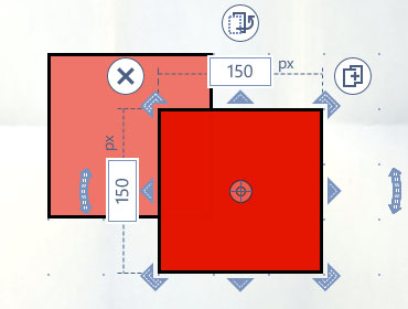
Move objects
To move an object to another position, it must to be activated at first. Now you can drag the object to the desired position.
17. POSITIONING OBJECTS ⮟
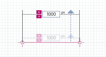
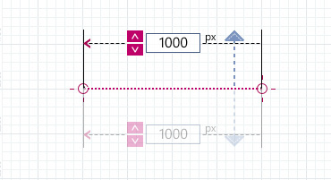
Position objects
While moving an object across the artboard, the x- and y-coordinates are displayed in the input fields of the dimension lines. To change the coordinates, the input field must be tapped. It becomes editable and the exact value can be entered.
18. SCALING OBJECTS ⮟
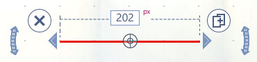
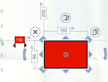
Scale objects
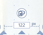
To resize an object, the bounding box provides eight scale handles.
The two handles on the left and right side of the bounding box are used to scale the object horizontally. The upper and the lower handles are used for vertical scaling. The corner handles allow simultaneous scaling in both directions. The object is scaled by dragging one of these handles in the desired direction. The aspect ratio is maintained if this is enabled in the App settings.
19 ROTATING OBJECTS ⮟
Rotate objects
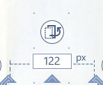
To rotate an object, the bounding box provides two rotation handles on both sides.
An object can be rotated clockwise or anticlockwise around its center point by dragging the left or right ‘rotation handle’ of the bounding box in the desired direction.
While rotating, the input fields show the current rotation angle. To change the rotation angle, the corresponding input field must be tapped in order to make it editable. The virtual keyboard opens and the new value can be entered directly.
20. MIRRORING OBJECTS ⮟
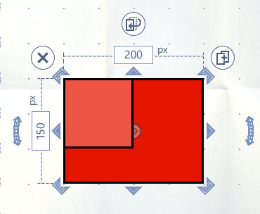
Mirror objects
To mirror an object, use the eight scale handles of the bounding box.
The two handles on the left and right side of the bounding box are intended to mirror an object horizontally. The upper and the lower ones are used to mirror it vertically.
The handles at the corners allow simultaneous mirroring in both directions.
The object is mirrored by dragging a scale handle to the opposite side of the mirror axis.
21. BUTTONS ⮟
Duplicate objects
By tapping the ‘clone button’ of the bounding box, an exact copy of the object is created and placed on the artboard.
Arrange objects
By tapping the ‘layer button’ of the bounding box, the object is moved either to the foreground or to the background related to the other objects. In this way, the visual hierarchy of objects on the artboard can be defined.
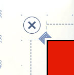
22. DELETING OBJECTS ⮟
Delete objects
To delete an object from the artboard, tap the ‘delete button’ of the bounding box.
Clearing the canvas
To delete all objects from the canvas at once, the ‘clear button’ of the upper toolbar is tapped. Now a new blank drawing area is available.

23. LAYER ⮟
Renaming layers
The name of a layer can be changed by double tapping. The text becomes editable and the name can be entered using the keyboard.

Asigning objects to layers
The handle (purple dots) on the right of each object layer allows you to drag it to another group layer. This is done by holding, moving and dropping the object layer onto the target group layer.
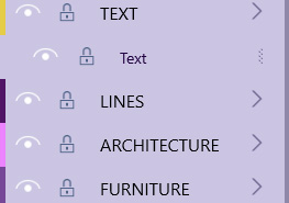
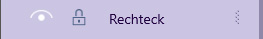
Showing and locking layers
When an object layer is tapped, the corresponding object is activated on the canvas. The same applies the other way round. When an object is activated on the canvas, the corresponding object layer is selected too.
In addition, when you select a main layer, all assigned objects are simultaneously activated on the canvas. They are equipped with a common bounding box that allows all activated objects to be moved or rotated together.
When the top layer is tapped, all existing (unlocked and visible) objects on the canvas are activated and can be moved or rotated together.
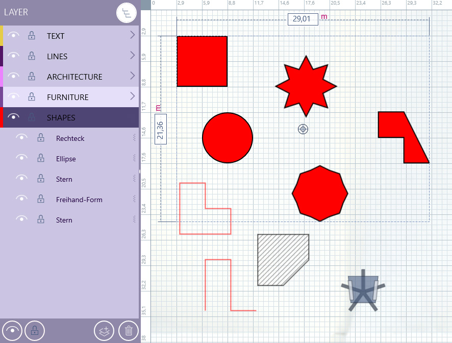
Layer functions
The footer area of the layer list provides two icons on the left which allow you to show/hide or lock/unlock all layers/objects on the canvas.
You can also add a new main layer or delete a selected layer from the list by clicking on one of the two buttons on the right. If a main layer is deleted, all related objects are deleted too.

24. GESTURES ⮟
Edit mode and gesture mode
In the top toolbar, two icons are available to switch between the edit-mode and the gesture-mode of the App.
In the edit-mode objects can be created or modified! Zooming or panning is not possible in this mode.
The gesture-mode is used to zoom in or out the view or even to move the artboard. Objects cannot be modified in this mode!
Zoom via touch gestures
Pinch gestures are provided to enlarge and reduce the view.
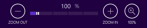
Zoom via zoom controls
The bottom toolbar contains a slider that allows you to zoom in or out. The smallest zoom level is 50%, the largest is 500%.
The two zoom buttons marked with +’ and -‘ on the left and right allow you to zoom in small, defined units.
The very right button resets the zoom level to 100%.
The textbox above the slider displays the current the zoom level value. If you tap on the text box, the value becomes editable and can be changed to the desired value.
Key strokes
If input devices such as a keyboard or a mouse are connected, scrolling and panning of the art board is possible via mouse wheel and key input.
If you press the’ CRTL’ key in edit mode while scrolling with the mouse wheel, you can zoom in or out the view.
Pressing ‘CRTL’ key and dragging with mouse in the edit-mode allows panning the view.
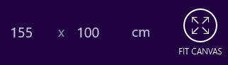
Canvas size
The size of the workspace depends on the individual display size of the computer monitor or tablet display. The two textboxes in the App toolbar display the width and the height of the artboard. If one of them is tapped, it becomes editable. The values can be edited using the keyboard.
The button on the right-hand side resets the size of the artboard to the display size.
25. UNDO & REDO⮟
Undo and Redo
At the top of the screen there are two buttons that allow you to undo and redo actions already performed.
The Undo button restores the previous state of an object. The redo button reverses the undo action.

26. SHORTCUTS ⮟
Key strokes
CTRL + S
CTRL + A
SHIFT + CLICK
ESCAPE
ENTER
CTRL + +
CTRL + –
CTRL + C
CTRL + V
CTRL + X
CTRL + MOUSE WHEEL
CTRL + 0 / CTRL + 1
CTRL + P
CTRL + Z
CTRL + Y
DELETE
Save project
Select all
Multi selection
Deselect
Confirm
Zoom in
Zoom out
Copy object
Paste object
Cut object
Zoom in / Zoom out
Zoom to 100%
Print
Undo
Redo
Delete object